Reduce Scrapping and Smelting, Promote Component Reuse > Unpowered, Hand Tools
> Woodworking Tools
> DuPage County
> Smt to dip adaptors, pcb for 15 ic's 20-28 pin smd
Smt to dip adaptors, pcb for 15 ic's 20-28 pin smd
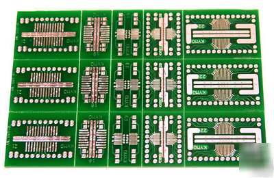
SMT -to- DIP Adapters PCB for 0.05" and 0.025" lead pitch
15 individual snappable IC carriers
direct-to-socket surface mount converters
PCB has V-scores, so individual tiles can be broken off by hand. Can use standard square pins, or machined pins. Header pins not included, but available separately.
Thermal lands provided to accomodate IC's with exposed metal thermal pads. These lands are "stitched" to the opposite side of the PCB with thermal vias to conduct heat away from the chip. These surfaces can also be used as ground planes in chips that don't have an exposed thermal pad. Their geometry is optimized to also permit using these lands for power bus and bypass capacitor mounting.
You can also purchase individual tiles, or higher pin-count tiles, available in my listings (search for "SMT")
Example of a finished adaptor, using machined header pins (pins not included), and standard square pins.
PCB contains 3 of each of the patterns shown below (enlarged):
For IC case: SOIC 8 to 16 pins / narrow and wide
Converts to: 0.300" DIP-14/16 socket
Thermal pad: all types supported, 2-side stiched /power bus
For IC case: TSOP, MSOP, PSOP, SSOP 8 to 16 pins / narrow and wide
For case: TSOP, MSOP, PSOP, SSOP 8 to 20 pins / narrow and wide
Converts to: 0.300" or 0.600" DIP-14/16/20 socket
Pin soldering: bottom (0.300" wide) or top (0.600" wide)
For case: SOIC 8 to 24 pins / narrow and wide
Pin soldering: bottom (0.600" wide) or top (0.700" wide)
For case: TSOP, MSOP, PSOP, SSOP 14 to 28 pins
Pin soldering: bottom (0.600" wide) or top (0.800" wide)
You insert the pins in a solderless breadboard to keep them firm and parallel. Then seat the carrier PCB on top of them and solder. This way, you can even get away with combining smaller header fragments ( a 3 pin and a 4 pin to make 7 in-line), and recycle what you already have.
Machined pins are ideal for breadboard use. They are as thin as most component leads, and will not stretch solderless contacts. Below: Machined Header pins. This is the best solution- double male pins. These are gold plated.
Styles #20, 21 and #22 use thru-hole top soldered pins, or bottom soldered pins. Top soldering is self explanatory, and can be seen in the photos above.
BOTTOM soldering allows the carrier to also act as a REDUCER, to bring the row spacing back to 0.300" or 0.600" for standard socket insertion. Other SMT systems require the use of an additional board, the "reducer" board, under the carrier PCB to accomplish this task (more work, more time, more cost, more materials)
Styles #18 and #19 are BOTTOM soldered carriers. Pins are surface-soldered on the bottom of the PCB, and do not emerge to the top side (except for the corner pins).
Narrower row spacing (0.300 or 0.600:) for direct socket insertion
Thermal lands under the IC for packages with exposed thermal pads
Header pins are cutt off or shortened, leaving only a short stub for soldering (except for the corner pins). Corner pins will be full length, soldered as usual, topside, and will keep the header anchored and aligned. Corner pins are soldered first, for alignment. See photos below.
Above: female machined sockets can also be used, if available, by inserting short lengths of thin wire in them. Let the corner wires protrude through the PCB, and bend all other wires outward for surface soldering. Use sufficient solder to fill the PCB hole, and fill the cup of the machine socket.
Industrial PCB assemblers use machines, not humans to place parts on a PCB. The solder is applied by silkscreening (printng like an ink) and melted by reflow systems. These systems only require IC solder pads as small as a tiny dot, to get the IC soldered in position every time with pinpoint accuracy.