Reduce Scrapping and Smelting, Promote Component Reuse > Unpowered, Hand Tools
> Diagnostic Tools
> Cook County
> Used
> HV200A-1 2 stage high voltage multiplier rectifier
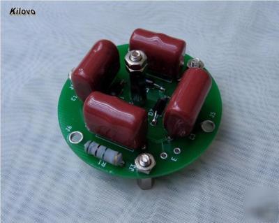
HV200A-1 2 stage high voltage multiplier rectifier
This is a single module high voltage multiplier with 2 voltage multiplier stages, maximum input AC voltage 200V (RMS) and 1KV maximum output.
This is a unique modular system for high voltage generation. Depending on application requirement, user can easily build up multiplier stack by using multiple multiplier modules, mechanically strong and electrically safe.
Maximum input AC voltage (RMS), 200V
Coupling capacitor, 1.0uF, 400V
Sensing resistor, 5MOhm/module
Physical dimension, 2" diameter, 1" high
E, jumper (connect HV sensing resistor to final HV output, solder on jumper E of last module only)
Following is coordinates of pin locations. They are useful for mounting the device.
J7, (0, 0), J1, (0, 0.88 ), J2, (0.762 , -0.44 )
J3, (-0.762 , -0.44 ), J4, (0.762 , 0.44 )
J5, (0, -0.88 ), J6, (-0.762 , 0.44 )
Piezo driving, photo multiplier tube driving, DC discharge experiment use.
Install 3mm standoffs at pin location J1, J2, and J3. These pins are responsible to mechanical supporting of the module and also electrical connections. Module should be mounted on an insulation material board or a conductive board with insulating washer. See pin assignment to make the connections, middle pin J7 is output.
Solder wire between the two pads of jumper E. This wire connects sensing resistor to middle output pin J7.
User can use a small resistance resistor as HV sensing output resistor. For example, if this resistor is 10KOhm, connects between J3 and ground, user can get high voltage signal 0-1.6V corresponds to output 0 - 800V across this sensing resistor.
2. Multiple module application
User needs to do all the same operation on the first module as single module application except solder jumper wire at E. Solder jumper wire E of the last module, to make sensing resistor string connect to final output high voltage.
Following is the explanation of how to mechanically and electrically connect modules. Suppose we have two modules that they are #N and #N+1 in the stack. First, we need to screw in 3 3mm metal standoffs at position J4, J5, and J6. Then put module #N on table, faces up. Put module #N+1 on top of #N, align the pins together, J1 to J1, J6 to J6. After this alignment, make module #N+1 clockwise 60 degree rotate. After this operation, we get J1 of #N+1 module connects to J4 of #N module; J2 of #N+1 module connects J5 of #N module; and J3 of #N+1 module connects to J6 of #N module. These are all correct connections between modules.
All sensing resistors are automatically connected together in series to form total sensing resistance 5MOhm x N, N is total module number.
User has two ways to generate AC signal with frequency a few KHz to 100KHz. If the application is on a temporary experiment setup, user can use a function generator to generate small power sine wave signal, and then use an audio power amplifier to amplify this signal to required power. The amplifier output drives a step-up transformer, with premier and secondary coil turn ratio about 1:100.
For a permanent setup, switching power circuit is the best way to generate high voltage AC voltage. User can refer PWM chip SG3525 data sheet to get an idea how to make this AC source.
Following curve shows a measurement of input AC and output DC of a 2 module unit (4 multiplier stages)