Reduce Scrapping and Smelting, Promote Component Reuse > Engine Powered
> Diesel
> DuPage County
> Used
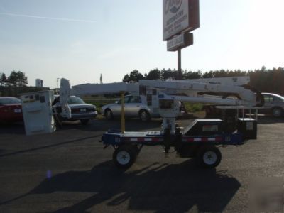
> 06 skylift with altec AT37-g bucket boom lift must see
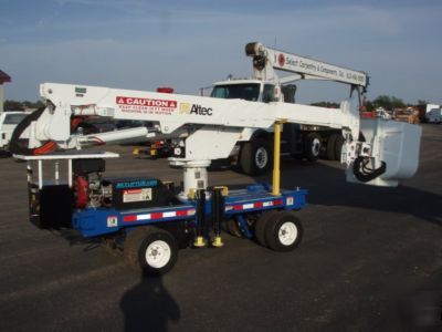
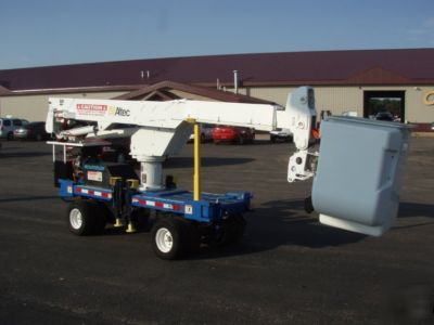
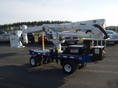
06 skylift with altec AT37-g bucket boom lift must see
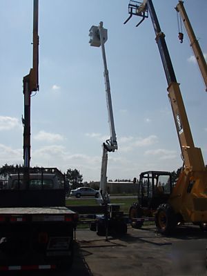
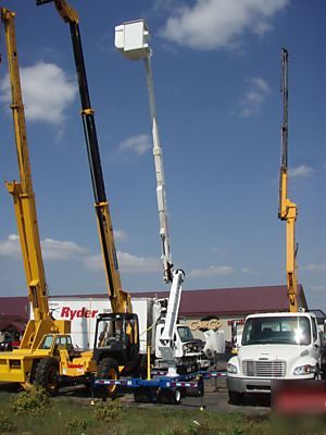
2006 SKYLIFT WITH ALTEC 37FT BUCKET BOOM
EXCELLENT FOR USE IN TIGHT WORK SPACES OR LOW CLEARANCE
* End Mounted 24 x 30 x 42 Inch Platform (300 lb Capacity)
* Full Pressure Controls on Side of Platform
* ISOControl 3-D Single Stick
* Open Center Hydraulic System
* Category "C" Rating Per ANSI A92.2
* Lower Controls Above Rotation
* Lower Controls Override Upper Controls
* Hydraulic Tool Circuit At Platform
* Bottom of Platform Height (A) 34 ft.
* Horizontal Reach (C) 28 ft.
* Lower Boom Articulation -3 to 82
* Upper Boom Travel -17 to 76
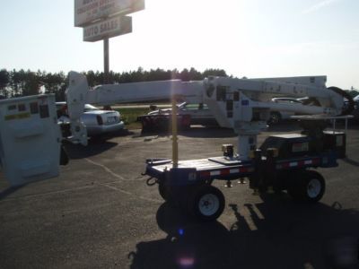
Chassis: Skylift Mini-Arborist
* 35 Inches Wide (Fits through Standard Gates)
* Dual Removable Wheels (Inner Wheels Solid Filled / Outer Wheels Air Filled)
* 20 HP Honda Engine (Electric Start)
* Conventional Steering (Least Amount of Turf Damage)
* Full Proportional Hydraulic Controls
* All Hydraulic Direct Motor Drive
* Outrigger / Boom Interlock
The machine base will fit through a 36 inch garden gate. The base is approximately 10 feet long and 28 inches high. The frame supports the power unit to drive the base and the boom. A hydraulic tank is located on the base.
The standard power for the base and aerial device will be a 13 HP BRIGGS AND STRATON gasoline engine driving a hydraulic pump and electric generator. The engine is electric start.
At each corner of the Mini-Derrick frame there is an outrigger that rotates out to extended position (manually), before extending HYDRAULICALLY down. Controls for the outriggers are at the lower control station. Front and rear valves are controlled independently.
The turret assembly shall be welded assembly with 0.63 inch thick sides and 1.00 inch thick base plate. The turret and pedestal will be fastened to the rotation system with 0.63 inch diameter grade 5 hex capscrews tightened to a specified torque lock to prevent loosening.
The rotation drive shall be a shear ball bearing with worm driving directly on helical gear teeth machined on the outer race. The worm must be self locking and hourglass shaped to engage multiple teeth at all times. The rotation bearing, worm and housing must be factory adjusted and will not require field adjustment.
The articulating lower boom shall be a minimum of 5 inch by 7 inch steel tube. The boom shall articulate from 6 degrees below horizontal to vertical by means of a 4.0 inch bore cylinder. A parallelogram linkage shall be provided to maintain the upper boom at a constant angle relative to the ground as the lower boom is raised.
The telescopic upper boom shall articulate from 14 degrees below horizontal to 77 degrees above horizontal by means of a 3.5 inch bore cylinder. A 30 inch length of the fiberglass boom shall be non-tracking over any slide pads or rollers providing a minimum insulation gap of 30 inches . Extended, the insulation gap shall be a minimum of 42 inches. The fiberglass boom will be filament wound using oven cured epoxy resin for consistent strength. The inner boom shall be dielectrically tested and rated per ANSI A92.2-1990 for Category C-46Kv and below, fully retracted.
Boom extension/retraction shall be accomplished with a hydraulic cylinder attached between the outer and inner boom. Holding valves in the extension cylinder must hydraulically prevent boom creep in both directions.
Hoses and control circuits shall be housed inside a plastic hose carrier housed inside the boom. The hose carrier and inner boom slide pads must be accessible for service without removing the inner boom from the outer boom.
A double acting 5 INCH BORE cylinder elevates the booms. The booms travel from 0 at the horizon to +80 above the horizon. A pilot operated holding valve is bolted to the elevation cylinder to prevent free fall in the event of hose failure.
Platform (Manually Rotated Platform)
A manual platform rotator shall be provided to allow positioning of the platform at 45 degrees or 90 degrees from the end of the boom. This shall provide for positioning of the platform for optimal work access. The platform shall be automatically leveled with a master/slave hydraulic leveling system. The slave cylinder shall include holding valves integral to the cylinder. The hydraulic leveling systems shall include an electrically controlled valve to allow platform leveling adjustments from the upper and lower controls. An additional valve assembly shall provide dual pilot operated check valves and dual circuit relief valves to prevent leakage from the system and to protect the system from damage. The platform shall be bonded into the step surface.
The upper controls shall include a single control handle for one handed operation of upper boom extension/retraction, upper boom raise/lower, rotation control and lower boom raise/lower. Electric switches in the control handle are to be environmentally sealed for weather protection. The upper controls shall be equipped with an emergency stop control at the platform. The lower controls shall be equipped with an emergency stop control at the platform. The lower controls shall include an environmentally sealed keyed master switch and environmentally sealed toggle switches capable of overriding the upper controls.
Contact us with any questions or if you need more information we have not listed. Feel free to contact us in person at (***)-393-3687 and ask for Tom.