Reduce Scrapping and Smelting, Promote Component Reuse > Complete Machines
> 1900 1920
> DuPage County
> Usb+serial port ICD2 pic in-circuit debugger+ module
Usb+serial port ICD2 pic in-circuit debugger+ module
Q: What's the difference between PIC-ICD2 and MPLAB-ICD2?
A: There is no functional difference between them and PIC-ICD2 is 100% compatible to MPLAB-ICD2. The only difference is the ICSP connector - Microchip uses RJ45 phone jack connector, we use 0.1" step connector
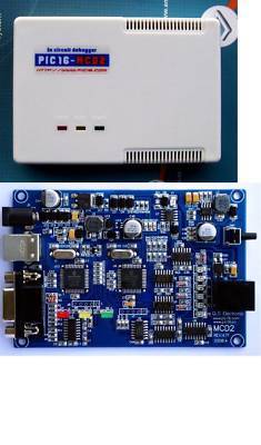
Q: Why on PIC-ICD2 there are teo ICSP connectors, which one I should use?
A: You should use the connector labeled ICSP-DEBUG next to USB connector, the other ICSP connector (down right on the picture) is the connector which we use to load PIC-ICD2 firmware and diagnostic the PIC-ICD2 during production tests.
Q: What should I know when connect PIC-ICD2 to target board.
A: It's very important your target PIC MCLR to not be connected directly to VCC! During the programming/debugging MCLR goes as high as 13VDC and if your target MCLR is connected directly to target VCC you will blow either PIC-ICD2 either your target board. Use always 10K pullup resistor from MCLR to VCC.
Q: What should I know when work PIC-ICD2 and RS232 port .
A: COM port should be set with HARDWARE FLOW CONTROL and FIFO buffers DISABLED!
An all-in-one debugger/programmer solution: MPLAB ICD 2 is a low cost, real-time debugger and programmer for selected PIC MCUs and dsPIC DSCs. Using Microchip Technology's proprietary In-Circuit Debug functions, programs can be downloaded, executed in real time and examined in detail with the debug functions of MPLAB. Set watch variables and breakpoints from symbolic labels in C or assembly source code, and single step through C source lines or into assembly code. MPLAB ICD 2 can also be used as a development programmer for supported MCUs.
The secret behind In Circuit Debugging is two dedicated hardware lines (microcontroller pins used only during debugging mode) that control In Circuit Serial Programming (ICSP ) of the device and, afterwards, debugging through proprietary, on-chip firmware. The ICD 2 debug features are built into the microcontroller and activated by programming the debug code into the target processor. There is some shared overhead expense that includes one stack level, some general purpose file registers and a small area of program memory when in the debug mode.
IMPORTANT NOTE: MPLAB ICD 2 requires minimal design guidelines be followed to ensure stable communications between the unit and the target.
USB MPLAB ICD2 MCD2 ICD2.5
New design Enhanced USB ICD2 PIC debugger and programmer for Microchip's
PIC and dsPIC digital signal controllers. Using the powerful user interface of the MPLAB IDE
(Intergrated Development Environment).
USB ICD2 In-circuit Debugger and Programmer:
* USB (Full Speed 2 M bits/s) & RS-232 interface to host PC
* Real time background debugging
* MPLAB IDE GUI (free copy included)
* Built in over-voltage/short circuit monitor
* Firmware upgradeable from PC
* Supports low voltage to 2.0 volts. (2.0 to 6.0 range)
* Diagnostic LEDs (Power, Busy, Error)
* Reading/Writing memory space and EEDATA areas of target microcontroller
* Programs configuration bits
* Erase of program memory space with verification
* Peripheral freeze-on-halt stops timers at breakpoints
* Built-in USB Reset self-reconnected function.
* High reliably ICs and Components.
* Compact design with mounting hole.
* Increased overcurrent protection
* Increased electrostatic protection
* Increased User Board first opened power protection
* Increased Users Board Overvoltage Protection
The MPLAB ICD 2 connects using USB or RS-232 between the design engineer's PC operating with MPLAB IDE and their product board (target) being developed. It acts as an intelligent interface/translator between the two, allowing the engineer to look into the active target board's microcontroller, viewing variables and registers at breakpoints with MPLAB watch windows. A breakpoint can be set to halt the program at a specific location. The program can be single-stepped or run at full speed. At breakpoints, data and program memory can be read and modified. Additionally, the MPLAB ICD 2 can be used to program or reprogram the Flash-based microcontroller while installed on the board.
Universal Programming Module(free):
1. This is an easy to use Universal Programming Module for ICD2,MCD2,ICD2.5
2. Using a clamp for the SOIC Support socket :SOT23-6(PIC10FXXX) SO-8 SO-14 SO-18 SO-28 TQFP44 PQFP44 PLCC44 TQFP64 DIP40
3. VPP can choose before VDD, ICD2 support internal oscillations and internal reset chip's repeated programming
4. We have to you DuPont lines for programming different chips (red DuPont lines*4,black DuPont lines*4,purple DuPont lines*1, yellow DuPont lines*1,white DuPont lines*1)
5. Have ICSP OUT interface, convenient to other target's internal oscillation and internal reset chip programming
6. 40-Pin 3M ZIF socket. ZIF on programmable chip package: DIP8, DIP14, DIP18, DIP20, DIP28, DIP40
Devices Support Details (MPLAB IDE 7.62 version):
"*" Devices Debugging needs Header Interface
"#" Devices with preliminary support
"*" Devices with preliminary support
1. USB & RS-232 PIC ICD2 In-circuit Debugger and Programmer.(PIC16-MCD2)
4. Universal Programming Module.
5. 1 x 6-Pin Individual ICSP Cable.
6. 1 x RJ12 Connection Cable.
8. Power supply(110-240 AC TO 9V DC)
Package Size: 290mm*220mm*80mm
We guarantee the item you purchase is the item we described here. If the arrives and is not as described, you may return the item for a refund. Returns cannot accepted for any other reason.
Items returned without an RMA (Return Material Authorization) will be refused.
A return request must be completed within 14 days after you receive the item.