Reduce Scrapping and Smelting, Promote Component Reuse > Antique Horse and Steam Powered
> Steam Tractors
> DuPage County
> New
> 12VOLT electronic timer relay on-delay 12V 24V [ssr out
12VOLT electronic timer relay on-delay 12V 24V [ssr out
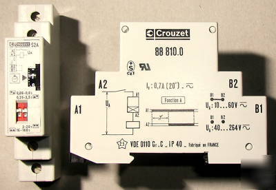
Power Requirements: Can be operated from ANY voltage from 10V to 264V ac or dc. For the range 10...60V ac/dc a short linking wire must be fitted between terminals B1 and B2
Output: Solid state. Max current load: 0.7A [for devices with higher current/load ratings the timer should be used to operate a suitable relay or contactor - see below].
Four timing ranges: 0.06sec~0.6sec / 0.25sec~2.5sec / 2sec~20sec / 16sec~160sec [range is set via two switches on the front of the unit]
Once a range is selected, fine adjustment within each range is possible using the "thumbwheel" dial. This adjustment is continuously "smoothly" adjustable - not in steps.
Function: Timing commences when power is connected - after the set time delay period the output to the load is switched ON. Output remains ON until power is removed. See diagram below: u represents power to unit and the bottom line represents the output. Where the unit is operated for less than time T the relay does not operate and when power is removed the timing is reset. [i.e at each operation it will always start the timing from zero.]
To generate an initial pulse. i.e. an output that turns ON as power is applied and then OFF at the end of the delay - it would be necessary to use the timer to switch an additional changeover relay.
Wiring: please enlarge the photo. It really is as simple as it looks - one wire in from the power source [A1] and one wire out to load [A2]. And an single permanently wired link [B1 to B2] for 10~60V ac/dc operation. [i.e. the timer is simply fitted in series with the load or an external relay coil]
Fitting: Clips to standard "consumer unit" type 35mm din rail. Can be conveniently mounted alongside regular MCBs.
Fitting Instructions: Electrical specifications and a numbered terminal layout plan and switching diagram are printed on the side of the timer. [see picture]
CONDITION: These have been out of production for quite a few years so possibly/probably systems pulls - I'm not sure. But clean, tidy and fully operational.
VERY IMPORTANT: This timer contains a highly reliable electronic [solid state] switch. Unlike a relay output - it has no mechanical contacts and will never wear out. However - it is suitable only for the switching of very small loads. The timer should not be used to directly switch highly inductive loads or to directly start or stop motors or to operate any load with a high initial starting [in-rush] current.
For switching loads with starting currents greater than 0.7amp it will be necessary to use the timer in combination with a suitable relay or contactor.
If required I can supply a range of suitable relays or contactors cheaply with the timer. Please contact me with your requirements i.e. operating voltage[s] and anticipated max Load etc.
In the rare instances where there is such a problem I am always more than happy to provide a full refund or replacement goods or where the item has been lost or damaged in transit I will pursue a claim against the carrier. I may in some unusual cases ask for proof of genuine complaint or for the goods to be returned before refund is given. Wherever a replacement is available the goods will be replaced. Returned goods must be received in reasonable condition before such a refund is issued. Misuse of goods or tampering will invalidate any guarantee.