Reduce Scrapping and Smelting, Promote Component Reuse > Complete Machines
> 1940 1960
> DuPage County
> Smt to dip adaptors, soic-8 to dip-8 converter smd, #14
Smt to dip adaptors, soic-8 to dip-8 converter smd, #14
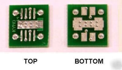
SMT -to- 0.100" DIP Adapter PCB
SOIC-8 to DIP-8 direct-to-socket converter
Breadboard and experiment with SMT parts in a way never possible before.
SUPPORTS IC'S WITH METAL THERMAL PADS
Row spacing: 0.300", ready for socket insertion
This listing is for style #14, shown below
Pins accepted: standard or machined
Thermal pad: all types supported, 2-side stiched
Takes standard 0.100 header pins for legs. Can use standard square pins, or machined pins. Header pins not included, but available separately.
Extra long smt fingers, for easy iron-soldering without touching the IC leads.
High quality FR4 double-sided, plated-thru and tinned holes, with conformal coating solder mask.
Thermal lands provided to accomodate IC's with exposed metal thermal pads. These lands are "stitched" to the opposite side of the PCB with thermal vias to conduct heat away from the chip. These surfaces can also be used as ground planes in chips that don't have an exposed thermal pad.
Example of a finished adaptor, using machined header pins (pins not included)
Graphic pattern of available converters below (enlarged):
Catalog of other available patterns
Below: the right way to solder pins to a carrier.
You insert the pins in a solderless breadboard to keep them firm and parallel. Then seat the carrier PCB on top of them and solder. This way, you can even get away with combining smaller header fragments ( a 3 pin and a 4 pin to make 7 inline), and recycle what you already have.
Machined pins are ideal for breadboard use. They are as thin as most component leads, and will not stretch solderless contacts. Below: Machined Header pins. This is what you need- double male pins. These are gold plated. Search our listings for "machined"
This is a BOTTOM solderd carrier. Pins are surface-soldered on the bottom of the PCB, and do not emerge to the top side (except for the corner pins).
More unobstructed space topside for easy soldering of the IC
Thermal lands under the IC for cases with exposed thermal pads
Shorter and more direct traces from IC to pins, for high frequency integrity.
#14 and #17 are bottom soldered. #15 and #16 are top soldered carriers (all thru-hole pins) but do not have the above features.
Header pins are cutt off or shortened, leaving only a short stub for soldering (except for the corner pins). Corner pins will be soldered as usual, topside, and will keep the header anchored and aligned. See photos below.
Remaining pins are surface-soldered on the bottom side, to the extra-large pads provided. Use minimal solder time to avoid melting the header frame. Use flux to get the solder flowing quickly.
Above: female machined sockets can also be used, if available, by inserting short lengths of thin wire in them. Let the corner wires protrude through the PCB, and bend all other wires outward for surface soldering. Use sufficient solder to fill the cup of the machine socket.
Why extra long SMT fingers for the IC?
Industrial PCB assemblers use machines, not humans to place parts on a PCB. The solder paste is applied by silkscreening (printng like an ink) and melted by reflow systems. These systems only require IC solder pads as small as a tiny dot, and they can get the IC soldered in position every time with pinpoint accuracy.
Humans don't work that way. If you use a soldering iron to accomplish this task, you need:
1. Space where to put the soldering iron when heating the pad, while maintaining a distance of 1-2 mm from the IC lead. (You should not touch the IC lead with the iron tip directly.)
2. Space to SEE what you are doing, so you can work accurately.