Reduce Scrapping and Smelting, Promote Component Reuse > Complete Machines
> 1940 1960
> DuPage County
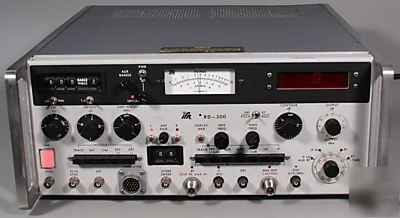
> Ifr rd-300 weather radar test set/simulator aircraft
Ifr rd-300 weather radar test set/simulator aircraft
IFR RD-300 Weather Radar Test Set for Aviation Testing/Simulation
The unit is guaranteed to work for 30 days, parts and labor.
The RD-300 is designed as a precision simulator-tester of aircraft weather radar instruments. The RD-300, in conjunction with the oscilloscope, can perform virtually all routine radar testing. Because the RD-300 is connected to the unit under-test through just one calibrated coaxial cable, there is no need to reconfigure the test equipment to measure different parameters.
The RD-300 features a signal generator system which automatically acquires and tracks the magnetron frequency to eliminate constant retuning of the signal generator to compensate for magnetron or signal generator drift. The signal generator is modulated to simulate storm cell echoes in several modes, including Contour Mode. Contour Mode is used for rapid calibration and checkout of contour threshold circuits. The range delay of these simulated storm cell echoes is calibrated in microseconds ( s) or nautical miles (NM). Multiple returns can be generated to check and adjust the radar range ring display. An auxiliary modulation mode developsd narrow, short range pulses for testing multimode radars.
Measurement of the magnetron frequency and PRF appears on the Digital Display (12). The magnetron condition and spectrum characteristics can be checked using the detector and disciminator outputs. Peak power measurements are possible with a full scale sensitivity of 12 kW (or 120 kW peaks with the external 10 dB attenuator).
The IF Signal Generator covers from 20 to 70 MHz and can be swept. The two-Volt-rms maximum output can be used for high level IF or AFC testing. Bandwidths and center frequencies are measured by the Marker Frequency Generator during swept IF tests. The RD-300 also features antenna simulator output, which allows the display assembly to be swept at a variable rate.
RF Signal Generator Specifications:
Variable Mode Frequency: Continuously variable from 9.295 GHz to 9.425 GHz.
Track Mode Frequency: Track magnetron frequency within +/-25 kHz (pulse width > 2 s); +/-100 kHz (pulse width < from 0.5 s to 2.0 s).
F Mode (during Track): Signal generator frequency may be offset +/-0.75 MHz from nagetron for AFC centering. Front panel meter reads F offset.
Output Power: -50 to -127 dBm in 1 and 10 dB steps calibrated at R/T plus 0 to 20 dB boost with CONTOUR control; accuracy +/-2 dB.
Aux RF Output: -20 to -127 dBm plus 0 to 20 dB boost with CONTOUR control. (Maximum power with full boost: -10 dBm).
Source VSWR at Input of R/T Unit Under Test: <1.25
IF Signal Generator Specifications:
Sweep Width: 0 to 40 MHz centered at counter reading.
Marker Frequency: Continuously variable from 20 to 70 MHz; may be displayed on frequency counter display.
Power: +20 to -130 dBm in 1 and 10 dB steps in two rangers; accuracy +/-1.5 dB
Modulation (IF or RF) Specifications:
Modes-Track (RF only): PRF same as radar-under-test.
Internal: PRF adjustable from 50 to 500 Hz.
EXT (+), EXT (-): External synchronization: Sine Wave or pulses, 2 to 5 V pl. 50 to 500 Hz.
Normal Mode: steps from 1 to 999 s for NM, 1 to 9 pulses.
Auxiliary Mode: continuously variable 2.1 to 29.6 s (0.17 to 2.4 NM)
Sync Out Signal: Simultaneous with signal generator pulse output or simultaneous with radar's magnetron pulse in Track Mode.
CONTOUR Mode (RF only): Amplitude of the signal generator pulse may be increased 0 to 20 dB above the attenuator setting.
Frequency Counter Specifications:
RF: Displays magnetron frequency in Track Mode and signal generator frequency in Manual or Auxiliary Modes; resolution 0.01 MHz.
IF: Displays IF frequency, center frequency in sweep mode, or marker frequency upon push button command; resolution 1 kHz.
PRF: Displays pulse repetition frequency of magnetron in Track Mode or of signal generator in Internal Modulation Mode; resolution 1 Hz.
Antenna Simulator Output: Variable scan rate 0 to 150 looks per minute. Variable in angle to +/-89 . Also variable in static position +/-89 . Has resolver, three phase synchro, and pot for antenna simulation and pitch or roll output with 8 lead for stablization platform testing and 45 offset for RCA units.
Range: 0.1 to 12 kW peak (or 1.0 to 120 kW peak with external 10 dB attenuator).
Accuracy: +/-0.6 dB from 2 to 12 kW peak.
Miscellaneous Outputs Specifications: (Used to Evaluate Magnetron Spectrum)
Detector: Detected magnetron signal used to check pulse shape with external oscilloscope.
Spectrum Analyzer: Attenuated RF sample of magnetron signal used to check pulse spectrum with external anlyzer.
Discriminator: Fast response discriminator output used to measure magnetron's frequency pushing using oscilloscope; 0.1 V/MHz sensitivity.
Power: 115/230 VAC, 50 to 400 Hz, 150 watts
Dimensions: 16.75" (42.55 cm) wide, 7.50" (18.05 cm) high, 18.38" (46.69 cm) deep. - does not include packaging.
Weight: Approx. 53 lbs. (24.09 kg) - does not include packaging.
* Picture 3 - Back of the Unit